Details on Component Data for Partial Network Start
Information about the dialog for technical data for the partial network start.
You are here:
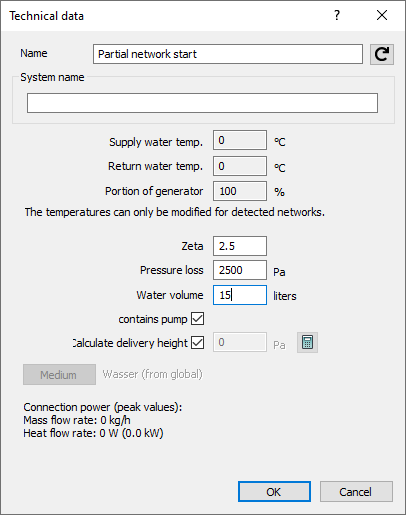
Name
Specifies the name of the component. You can modify the name. Clicking  restores the default setting.
System name
Enter systems a name for a better distinction. This name will be displayed in the calculation dialog when selecting a system. The data will be automatically transferred to the remaining heat or cooling generators.
Supply water temperature, Return water temperature
In the heat- or chill generator, specify the supply- and return water temperature for the entire pipe network. If multiple boiler systems are concerned, the data will be automatically transferred to the remaining heat generators.
Portion of generator
For multiple boiler systems, enter here the portion of the mass flow rates which is supposed to be covered by the individual heat or chill generator. At first, the default value of the portion is 100 %. You may split the portion of the mass flow rates so that the sum of all heat generators is 100 %. Likewise, redundant generators with a portion of 100 % each are possible. Moreover, mixed forms are possible: A part of the generators sums up to 100 %, to which one or several redundant generators with 100 % each are added. The sum of the mass flow rates of all generators ought to be 100% or a multiple thereof, else, a notification will be displayed in the report.
Zeta value, Pressure loss
With respect to this parameter, you may set either a fixed Zeta value for the heat/cooling generator or a fixed, absolute pressure loss in Pa.
Water volume
Enter the water volume of the heat or cooling generator here. This value will be used for the calculation of the system volume and for the dimensioning of the diaphragm expansion tank. If the water volume has not been specified, a report will be issued during calculation. This only occurs with a diaphragm expansion tank installed.
Contains Pump
Enabled: In the calculation, the presence of a pump is simulated for the partial network downstream of the partial network start. The capacity of the pump is determined in the calculation, but can also be adjusted manually. A click on  resets the pump capacity to the value determined in the calculation. If another pump is installed in the partial network downstream of the partial network start, a warning message regarding an excess number of pumps in the flow path appears in the calculation.
Disabled: In the calculation, no pump is simulated for the partial network downstream of the partial network start. If no pump is installed, an error message appears in the calculation and the network cannot be calculated. The installation of a pump in the partial network downstream of the partial network start is required.
Partial network start with connection
If the partial network start is connected to a partial network end, the dialog is reduced to the section Connection. Three additional Buttons will then be displayed. Click Unfix to remove the connection and the dialog will be reset to the original view with all component data. Use button to  to show the connected partial network in the model. The program zooms in on the part and also marks the position with an arrow. After clicking the button
  , the program displays both partial network start and partial network end of the connection and marks the connection with a broken line. The partial network end is marked additionally highlighted with an arrow in this view.