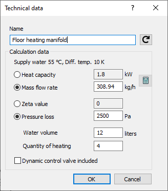
Details on Technical Data for Floor Heating Manifold
Information about the component data dialog for floor heating manifold.
The panel heating manifold is considered a consumer or an ending component in Pipe Network Calculation Heating. If heating circuits are connected to the heating manifold, they are not detected with Pipe Network Calculation Heating. The heating manifold contains all the technical data of the heating circuits required for the calculation. If you have drawn in the heating manifold from LINEAR Building, the data from the calculation is taken over from LINEAR Building and cannot be changed in this technical data dialog. If the data has changed, click Draw again in LINEAR Building. You can then update the manifold. You do not have to place the manifold again. The data is updated.
You are here:

Name
Specifies the name of the component. You can modify the name. Clicking  restores the default setting.
Calculation data
Heat capacity, Mass flow rate: You can enter either the mass flow rate or the heat capacity. The other value is automatically calculated.
Zeta value, Pressure loss: You can enter either the zeta value or the pressure loss. The pressure loss is transferred from LINEAR Building. If a dynamic regulating valve is included, the additional pressure losses from the network are added.
Water volume: Water volume will be used to calculate the system volume and for dimensioning the diaphragm expansion tank heating (DETH). If the water volume has not been specified, a report will be issued during calculation. This only occurs with a diaphragm expansion tank installed.
Dynamic control valve included
If the manifold is drawn from LINEAR Building, it can already contain a dynamic control valve depending on the used panel heating system. This option is then activated automatically. In this case, you no longer need to draw a control valve in front of the manifold. It is automatically balanced in LINEAR Building. The additional pressure losses from the network are added to the manifold. The settings can be taken from the calculation of LINEAR Building.
These non-drawn control valves are not listed in the printout regulating valves.