About Virtual Components
Explains the concept of virtual components in pipe and duct network calculations.
A pipe or duct network is - depending on the number of ending components (e.g. radiators or air outlets) - more or less branched. In order to structure such a network hydraulically clearly , the individual components between 2 branches are combined into so-called section parts. Also the first and last section on the way from a source (such as a boiler or fan) to a ending component is a partial section in each case. Superordinately, each flow path to its ending component results from a compilation of successive section parts.
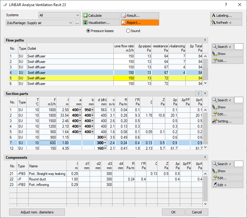
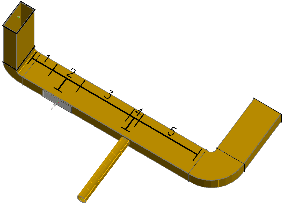
Usually you have a counterpart in the drawing or model for each component in the calculation. The exception, however, are branches which are not created by inserted branches, but by sockets or air grille on continuous pipes or ducts.
In such cases, hydraulic branching situations arise to which no corresponding component can be assigned in the drawing or in the model. Here, so-called “virtual” components are created for the calculation and marked in the component list with the prefix “>”.


Virtual components can be edited like all other components in the component dialog, except for the material. However, they do not appear in component lists because they are only relevant for the calculation.
This virtual component mechanism also applies to combination components such as combined supply and extract air units or heat exchangers. For the calculation, these are divided into two virtual ventilation devices or one heater and one cooler each.
Since only those components can be labeled that are in the drawing or in the model, all components with virtual sections get the calculation data of the virtual section with the largest volume flow.