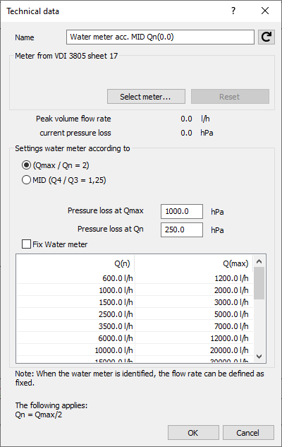
Details on Technical Data for Water Meter
Information about the technical data dialog for water meter.
For the calculation of pressure loss of a meter, an operating point is required which is determined automatically conforming to standards and is based on the current peak flow rate.
You are here:

Name
Specifies the name of the component. You can modify the name. Clicking  restores the default setting.
Meter from VDI 3805 sheet 17
Select meter ...: If a suitable data set has been installed, you can select a manufacturer water meter via the Select meter… button. After selection, the model is displayed in the technical data dialog.
Reset: Once a manufacturer model has been selected, the Reset button is activated. This allows you to remove manufacturer model and reset the meter to neutral data.
Data
After calculation, the peak volume flow and the current pressure loss of the meter are displayed.
Settings
You have the choice between design according to Q(max) and MID.
Water meter (Qmax / Qn = 2):
-
Pressure loss at Q(max): The maximum Pressure loss can be entered.
-
Pressure loss at Q(n): The Pressure loss at Q(n) is calculated and entered automatically.
Water meter according MID (Q4 / Q3 = 1,25): Water meters can also be designed according to current MID approval. The table below then shows the design relevant values Q3 and Q4.
-
Pressure loss at Q4: The pressure loss at Q4 can be entered.
-
Pressure loss at Q3: The pressure loss at Q3 is calculated and entered automatically.
SP 30.13330.2020
This option is automatically displayed and selected if you selected the Russian potable water standard SP 30.13330.2020 as the method in the Settings.
Fix water meter
If you want to define a specific operating point for determining the pressure loss, activate Fix Water meter and select Q(max) and Q(n) or Q3 and Q4 from the table for the desired operating point.
Note that the calculated peak flow rate should be between Q(max)/2 and Q(max). The calculated peak flow rate is shown after calculation of the network.