Projektowanie instalacji gazowych dla AutoCAD
Dzięki rozwiązaniom LINEAR gwarantowany jest ciągły Workflow w projektowaniu systemów gazowych. Od koncepcji, przez obliczenia sieci rurociągów, po szczegółowy projekt 3D: Stwórz projekt MEP szybko i wydajnie dzięki LINEAR w AutoCAD lub LINEAR CADinside.
LINEAR Workflow
Wejście:
Wymagania dotyczące dostaw do budynku
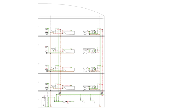
Wyjście:
Obliczalny projekt schematu
Etapy pracy:
- Tworzenie tabeli kondygnacji
- Ręczne tworzenie schematów za pomocą pasków narzędzi i określonych poleceń edycji
- Generator schematów do przeciągania i upuszczania oraz automatycznego rysowania
Wejście:
Plan architektoniczny
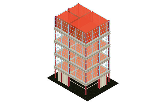
Wyjście:
Model do dalszego projektowania MEP, w tym poziomów i pomieszczeń
Etapy pracy:
- Odwoływanie się do plików DWG, DXF lub PDF od architekta
- Tworzenie tabeli kondygnacji
- Tworzenie modelu architektonicznego do dalszej budowy
Wejście:
Model dla projektu MEP, w tym poziomów i pomieszczeń
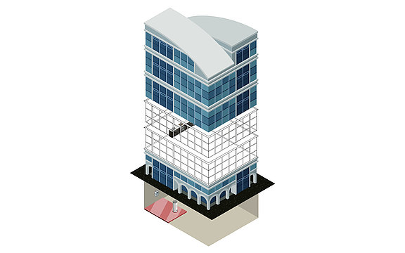
Wyjście:
Model MEP z komponentami gazowymi
Etapy pracy:
- Wybór odbiorników gazu jako komponentów neutralnych lub z obszernych bibliotek CAD producentów
- Łatwe umieszczanie w modelu za pomocą specjalnych poleceń rysowania
- Integracja komponentów systemu (np. przyłączy domowych, monitorów przepływu gazu, liczników, armatury)
Wejście:
Model MEP z umieszczonymi komponentami gazowymi
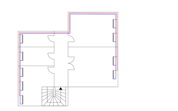
Wyjście:
Model MEP z obliczalną siecią (izometryczny lub plan piętra)
Etapy pracy:
- Projektowanie sieci rurociągów 2D lub izometrycznych przy użyciu poleceń konstrukcyjnych oszczędzających czas
- Automatyczne podłączanie wszystkich odbiorników
- Projektowanie systemu w sposób neutralny lub z pomocą obszernych bibliotek CAD producentów
Wejście:
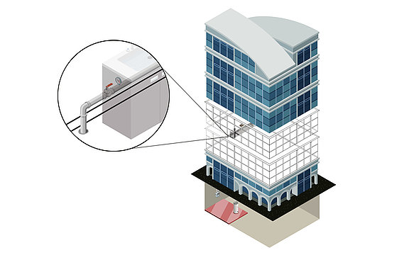
Model architektoniczny dla projektu MEP wraz z poziomami
Wyjście:
Szczegółowy model 3D
Etapy pracy:
- Szczegółowy projekt rury
- Automatyczne funkcje trasowania z podglądem możliwych alternatyw
- Projektowanie systemu w sposób neutralny lub z pomocą obszernych bibliotek CAD producentów
- Późniejsze umieszczanie komponentów z dopasowanymi przejściami i kołnierzami
- Automatyczne skręcanie całej konstrukcji (śruby, nakrętki, podkładki) z pełnym przeniesieniem do listy części
- Wstępne definiowanie materiałów izolacyjnych i pokazywanie/ukrywanie ich z przeniesieniem do listy części
- Kontrola kolizji w czasie rzeczywistym
- Ręcznie lub automatycznie przypisywane numery artykułów
- Listy materiałowe, listy części z numerami artykułów, listy cięcia rur, listy pozycji
Wejście:
Schemat, model 2D lub 3D
Wyjście:
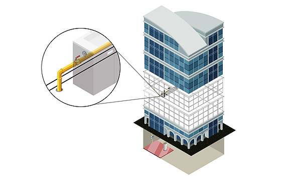
Model MEP ze zoptymalizowanym systemem gazowym (schemat, 2D lub 3D)
Etapy pracy:
- Określenie specyfikacji istotnych dla obliczeń (np. przypisanie materiałów rur, monitorów przepływu gazu)
- Porównanie wariantów przy użyciu zweryfikowanych zestawów danych producenta (np. systemów rur)
- Obliczanie istniejących sieci poprzez ustalenie pojedynczych lub wszystkich wymiarów
- Ponowne wymiarowanie sieci gazociągów na podstawie obliczeń
- Kolorowe wyświetlanie wszystkich wyników bezpośrednio w modelu
- Automatyczne generowanie 3D podczas tworzenia systemu w 2D (krok 4 - wariant 1)
Wejście:
Obliczona i zoptymalizowana sieć gazociągów
Wyjście:
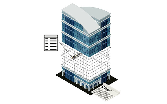
Końcowy projekt gazowy, w tym model do przeniesienia do modelu koordynacyjnego i wyniki obliczeń wraz z listami materiałów.
Etapy pracy:
- Zapisywanie wszystkich danych wejściowych i wyników obliczeń w modelu
- Publikacja wybranych wartości jako danych składowych
- Automatyczne etykietowanie modelu
- Dodawanie własnych parametrów i metainformacji
- Wydruk wyników w znormalizowanej formie
- Transfer wyników i modelu we wszystkich odpowiednich formatach
Input:
Wymagania dotyczące dostaw do budynku

Output:
Obliczalny projekt schematu
Arbeitsschritte:
- Tworzenie tabeli kondygnacji
- Ręczne tworzenie schematów za pomocą pasków narzędzi i określonych poleceń edycji
- Generator schematów do przeciągania i upuszczania oraz automatycznego rysowania
Input:
Plan architektoniczny

Output:
Model do dalszego projektowania MEP, w tym poziomów i pomieszczeń
Arbeitsschritte:
- Odwoływanie się do plików DWG, DXF lub PDF od architekta
- Tworzenie tabeli kondygnacji
- Tworzenie modelu architektonicznego do dalszej budowy
Input:
Model dla projektu MEP, w tym poziomów i pomieszczeń

Output:
Model MEP z komponentami gazowymi
Arbeitsschritte:
- Wybór odbiorników gazu jako komponentów neutralnych lub z obszernych bibliotek CAD producentów
- Łatwe umieszczanie w modelu za pomocą specjalnych poleceń rysowania
- Integracja komponentów systemu (np. przyłączy domowych, monitorów przepływu gazu, liczników, armatury)
Input:
Model MEP z umieszczonymi komponentami gazowymi

Output:
Model MEP z obliczalną siecią (izometryczny lub plan piętra)
Arbeitsschritte:
- Projektowanie sieci rurociągów 2D lub izometrycznych przy użyciu poleceń konstrukcyjnych oszczędzających czas
- Automatyczne podłączanie wszystkich odbiorników
- Projektowanie systemu w sposób neutralny lub z pomocą obszernych bibliotek CAD producentów
Input:
Model architektoniczny dla projektu MEP wraz z poziomami

Output:
Szczegółowy model 3D
Arbeitsschritte:
- Szczegółowy projekt rury
- Automatyczne funkcje trasowania z podglądem możliwych alternatyw
- Projektowanie systemu w sposób neutralny lub z pomocą obszernych bibliotek CAD producentów
- Późniejsze umieszczanie komponentów z dopasowanymi przejściami i kołnierzami
- Automatyczne skręcanie całej konstrukcji (śruby, nakrętki, podkładki) z pełnym przeniesieniem do listy części
- Wstępne definiowanie materiałów izolacyjnych i pokazywanie/ukrywanie ich z przeniesieniem do listy części
- Kontrola kolizji w czasie rzeczywistym
- Ręcznie lub automatycznie przypisywane numery artykułów
- Listy materiałowe, listy części z numerami artykułów, listy cięcia rur, listy pozycji
Input:
Schemat, model 2D lub 3D

Output:
Model MEP ze zoptymalizowanym systemem gazowym (schemat, 2D lub 3D)
Arbeitsschritte:
- Określenie specyfikacji istotnych dla obliczeń (np. przypisanie materiałów rur, monitorów przepływu gazu)
- Porównanie wariantów przy użyciu zweryfikowanych zestawów danych producenta (np. systemów rur)
- Obliczanie istniejących sieci poprzez ustalenie pojedynczych lub wszystkich wymiarów
- Ponowne wymiarowanie sieci gazociągów na podstawie obliczeń
- Kolorowe wyświetlanie wszystkich wyników bezpośrednio w modelu
- Automatyczne generowanie 3D podczas tworzenia systemu w 2D (krok 4 - wariant 1)
Input:
Obliczona i zoptymalizowana sieć gazociągów

Output:
Końcowy projekt gazowy, w tym model do przeniesienia do modelu koordynacyjnego i wyniki obliczeń wraz z listami materiałów.
Arbeitsschritte:
- Zapisywanie wszystkich danych wejściowych i wyników obliczeń w modelu
- Publikacja wybranych wartości jako danych składowych
- Automatyczne etykietowanie modelu
- Dodawanie własnych parametrów i metainformacji
- Wydruk wyników w znormalizowanej formie
- Transfer wyników i modelu we wszystkich odpowiednich formatach
Dostępne opcje
Projekt architektoniczny
- Proste narzędzia do tworzenia ścian, okien, drzwi, dachów itp. w oparciu o wiele formatów dokumentów, takich jak DWG, DXF, PDF, PNG lub JPEG.
Wybór języka dla interfejsu użytkownika i wydruków
Zapewniamy nie mniej niż siedem języków, których można używać i łączyć jako interfejs lub język drukowania. Umożliwia to planowanie w jednym języku i drukowanie w innym. Jest to ogromna zaleta, szczególnie w przypadku projektów międzynarodowych, ponieważ nie ma potrzeby wykonywania czasochłonnych tłumaczeń. Pakiety językowe nie wiążą się z żadnymi dodatkowymi kosztami.
Obecnie obsługiwane są następujące języki:
- Niemiecki
- angielski, niemiecki
- francuski, niemiecki
- holenderski
- rosyjski
- turecki
- włoski
- Polski w przygotowaniu (2025)
Obsługiwane standardy
Firma LINEAR zawsze opowiadała się za obliczeniami i projektowaniem zgodnym z normami. Ważne jest dla nas, aby zawsze oferować najnowsze standardy i stale poszerzać naszą ofertę norm krajowych i międzynarodowych. Aktualny przegląd wszystkich obsługiwanych norm można znaleźć w naszej bazie wiedzy pod adresem Knowledge Base.
Narzędzia FM
- Importowanie i eksportowanie informacji do zarządzania obiektami
- Importowanie informacji z baz danych FM
Interfejs IFC
- Import architektury w formacie IFC
- Eksport IFC z uwzględnieniem wszystkich metadanych
- Wybór transakcji, które mają być uwzględnione w eksporcie
Równoważenie hydrauliczne złożonych systemów
- Obliczenia hydrauliczne z transferem danych wydajności z parametrów rodziny
- Obliczanie kilku systemów w jednym modelu
- Obliczanie sieci z kilkoma poziomami sterowania
- Uwzględnienie nie tylko sieci dystrybucyjnych, ale także generatora
Szczegółowy projekt sieci rur 3D
- Planowanie rurociągów z funkcją trasowania i klasami rur do tworzenia armatury z milimetrową precyzją (zintegrowane projektowanie gradientów)
- Automatyczne łączenie rurociągów z przenoszeniem mediów, materiałów, wymiarów i poziomów ciśnienia.
- Generator kolektorów do tworzenia zespołów z pompami i zaworami, a także konfiguratory zbiorników, płytowych wymienników ciepła i innych urządzeń.
- Wstawianie komponentów z odpowiednimi przejściami i kołnierzami do istniejących systemów
- Kontrola kolizji w czasie rzeczywistym
- Automatyczne generowanie 3D obliczonych projektów 1-liniowych
- Edytor połączeń dla własnych komponentów 3D
- Automatyczne podłączanie rurociągów, w tym transfer mediów, materiałów, wymiarów i poziomów ciśnienia
- Automatyczne skręcanie całej konstrukcji (śruby, nakrętki, podkładki) z pełnym przeniesieniem do listy części
- Wstępne definiowanie materiałów izolacyjnych i pokazywanie lub ukrywanie ich z przeniesieniem do listy części
- Generator rozdzielaczy do tworzenia zespołów, w tym pomp i armatury
- Uwzględnianie potrąceń dla spawów, uszczelek i głębokości wsuwania lub połączeń śrubowych
- Ręcznie lub automatycznie przypisywane numery pozycji
- Listy materiałowe, listy części z numerami pozycji, listy cięcia rur, listy pozycji
Lista części z numerami artykułów
- Przejrzyste i zrozumiałe wyniki obliczeń oraz kompletne zestawienia ilościowe
- Szczegółowe listy części z numerami artykułów i testami materiałów
- Zestawienia ilości i listy części w różnych formatach wyjściowych (wydruk Windows, Excel, tekst, UGS, GAEB, ASD)
Obliczanie sieci rur, w tym przedmiarowanie
- Automatyczne obliczanie i wymiarowanie wszystkich elementów sieci gazowej
- Rozbudowane opcje ustawień warunków brzegowych obliczeń, takich jak wartości graniczne prędkości, władze zaworów, aktywne średnice rur, stałe wymiary rur i opór tarcia rur (wartość R).
- Określanie i porównywanie wariantów materiałów i komponentów rur, w tym oryginalnych zestawów danych producenta z rzeczywistymi właściwościami produktu
- Obliczenia bezpośrednio w modelu, w tym przedmiarowanie
- Obliczanie sieci gazowej zgodnie z TRGI 2018, TRGI 2008 / DVGW G600, DVGW G617, ÖVGW G11 i TRF 2012
- Obliczenia w każdej fazie planowania bezpośrednio z modelu
- Obliczenia zgodnie z TRGI dla systemów o ciśnieniu roboczym do 100 mbar
- Obliczenia dla systemów przemysłowych o ciśnieniu roboczym do 5 barów
- Obliczenia z rzeczywistymi właściwościami produktu przy użyciu zestawów danych od wiodących producentów
- Wprowadzanie wartości materiałowych (metan, butan, biogaz)
- Możliwość automatycznej konfiguracji monitora przepływu gazu
- Interfejs dla zestawów danych zaworów, zaworów odcinających, regulatorów różnicy ciśnień, regulatorów przepływu, zaworów regulacyjnych, zaworów sterujących i rezystorów stałych
- Alternatywne obliczenia według Zanke'a, Prandtla Colebrooka i Prandtla-Kármána
- Możliwość projektowania sieci przewodów sprężonego powietrza
- Wizualizacja wyników za pomocą liNear Data Coloring (np. wymiary, materiały, prędkości, straty ciśnienia itp.)
Automatyczne wykrywanie sieci rur
- Rozpoznawanie narysowanych rur bezpośrednio w modelu i analiza systemu
- Rozpoznawanie wszystkich zintegrowanych komponentów
- Uwzględnianie danych technicznych zintegrowanych z modelem
- Rozpoznawanie skonstruowanych wymiarów do opcjonalnego uwzględnienia w obliczeniach sieciowych
- Proste mapowanie komponentów innych firm do uwzględnienia w obliczeniach sieciowych
Producent komponentów poprzez CAD-Browser
- Rozbudowane biblioteki CAD ze sprawdzonymi komponentami od naszych licznych partnerów branżowych
- Ponad 6 miliardów możliwych komponentów i ich kombinacji
- Bezpośrednie umieszczanie oryginalnych komponentów producenta w modelu
- Wiele trybów umieszczania (umieść, wstaw, zamień)
- Konfiguratory złożonych kombinacji komponentów (np. systemy kaskadowe)
- Integracja danych technicznych i handlowych (np. numerów artykułów i jednostek opakowaniowych)
- Rozpoznawanie i uwzględnianie w obliczeniach sieciowych
Kontrola widoczności
Kontrola widoczności za pomocą jednego kliknięcia:
- Części budynku
- kondygnacje
- branż
- Grupy komponentów (np. systemy, izolacja itp.)
Stół piętrowy
- Automatyczny import kondygnacji z modelu architektonicznego
- Kontrola kondygnacji w płaszczyźnie konstrukcyjnej / obszarze przesunięcia (+/-)
- Proste tworzenie kondygnacji i płaszczyzn roboczych
Generator schematów
- Tworzenie kompletnych i obliczalnych schematów metodą „przeciągnij i upuść
- Tworzenie schematów nawet bez doświadczenia CAD
- Automatyczne rysowanie schematu
- Definiowanie przekrojów i zagięć
- Proste kopiowanie kondygnacji i przebiegów rur
- Definiowanie komponentów (np. zaworów i pomp) znajdujących się już w generatorze
- Zapisywanie i importowanie istniejących konfiguracji
Narzędzia budowlane
- Trasowanie rur, w tym określanie klasy systemu z automatycznym przenoszeniem mediów i odległości we wszystkich typach widoku
- Automatyczne łączenie rur wraz z niezbędnymi przejściami (autorouting)
- Automatyczne łączenie trójników
- Polecenie skoku linii do rozwiązywania kolizji
- Rozbudowane biblioteki symboli (z możliwością dowolnej rozbudowy)
- Animowany kreator hydrauliczny do tworzenia obwodów hydraulicznych
- Planowanie rurociągów 2D i generator rozdzielaczy 2D do szczegółowego planowania
- Praca na dokumentach 2D i 3D: DWG, DXF, PDF, JPEG, PNG itp., w tym asystent projektowania konstrukcji dachowych
- Planowanie szczelin i przebić
- Listy części z krótkimi i długimi tekstami
- Konfiguratory grzejników, rozdzielaczy, zbiorników i stacji domowych
- Polecenie trasy do budowy kilku rur jednocześnie
- Asystent ogrzewania panelowego do układania i podłączania obwodów
- Automatyczne etykietowanie i tworzenie legend