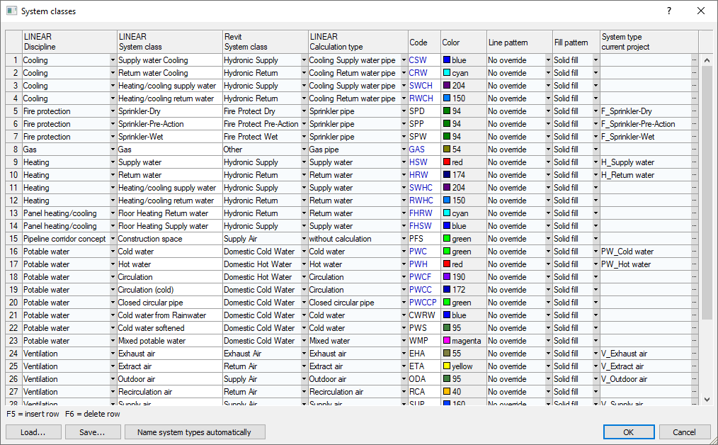
Details on the System Classes Dialog
Information about the System classes dialog.
The System classes dialog contains all LINEAR system classes and their properties. This information is used to define the system types. Each system class is assigned a discipline, a Revit system class, and a LINEARcalculation type. Furthermore, an abbreviation and the color representation of pipes and ducts are defined. You can change the LINEAR system classes and create new LINEAR system classes.
You are here:
Applies to: Heating, Cooling, Potable Water, Waste Water, Ventilation, Panel Heating/Cooling, Gas, Fire Protection.

Different combinations of discipline name, discipline code, system class name, or system class code can be used to describe the system type. You define the configuration for the system type name in the Options.
LINEARDiscipline
Determines which discipline the LINEAR system class belongs to. The name of the discipline can be changed in the Disciplines dialog.
LINEAR-System class
A distinction is made between LINEAR system classes and Revit system classes. The Revit system classes are fixed and can not be extended. In order to be able to use additional system types that are required for the Pipe and Air Duct Network Calculation, there are the LINEAR system classes. Each LINEAR system class is assigned to a Revit system class and a calculation type.
The name of the LINEAR system class can be freely defined and is usually used for the name of the system type. The number of LINEAR system classes is not limited. LINEAR-system classes can be created and changed.
Revit-System class
Revit-System classes are fixed and cannot be changed or extended. Additional system classes are required for the Pipe and Air Duct Network Calculation. This is why there are LINEAR system classes. Define the appropriate Revit system class for the new LINEAR system class here. If there is no suitable Revit system class, select Other.
LINEARCalculation type
The LINEAR calculation type determines how the pipes and ducts are treated in the Pipe and Air Duct Network Calculation. A calculation type is assigned to each system type so that the system type is interpreted correctly in the Pipe and Air Duct Network Calculation.
Code
The code is an abbreviation of the LINEAR system class. The code can be freely defined when creating a new LINEAR system class.
Color
Defines the color used to display the elements of this system type.
Line pattern
Defines the pattern with which the lines of the elements of this system type are displayed.
Fill pattern
Defines the pattern with which the areas of the elements of this system type are filled. If Area fill is selected, the areas are filled with the color from the System classes dialog.
System type current project
This field is empty until a system type is used for the first time. The system type is only created and assigned from discipline and system class when a pipe, duct or component is constructed.
Load...
Loads a self-generated set of system classes.
Save...
Saves the current settings of the System classes dialog. Changes are also available in other projects and can be transferred.
Name system types automatically
If the current project was not created with LINEAR Solutions, the system types it contains may differ from LINEAR scheme. With this function, the system types are automatically renamed according to the settings in the System classes dialog and the LINEAR options and can thus be used for Pipe and Air Duct Network Calculations.