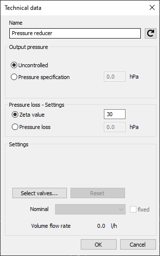
Details on Technical Data for Pressure Reducers
Information on the technical data dialog for Pressure reducers.
The pressure reducer or pressure closed-loop controller has two connection points each of which are connected to a pipe. Generally you will initially draw the pipeline and then add the component to the pipe. The pipeline will be interrupted automatically and the component is connected correctly directly to the pipeline.
You are here:
It is recommended to analyze the zonal structure of the pressure conditions before constructing the actual pipe network in order to define which areas have to be provided with a pressure reducer and which areas are located in a standard pressure zone where a pressure reducer is not necessary. Both areas should be separated in the pipe network.
If a pressure reducer is only inserted into the hot or cold water partial network, the consumers connected downstream will be in different pressure zones. This can lead to significant temperature fluctuations at the discharge taps.

Name
Specifies the name of the component. You can modify the name. Clicking  restores the default setting.
Output pressure
At first the pressure reducer is calculated with the status uncontrolled, i.e. the reducer is completely opened and acts passively in the pipe network (without effects on the pipe network).
Switch to Pressure specification and enter the output pressure that is supposed to adjust itself downstream of the pressure reducer.
Pressure loss – settings
In this dialog box you either set a fixed Zeta value for the pressure reducer or a fixed pressure loss in hPa. To that end, activate the respective radio button to the left of the edit field.
Settings
In case a pressure reducer has already been added in the armature preselection, the corresponding component data will be displayed here. You may also assign the desired valve by clicking the button Select valve.... If a valve has already been assigned, click the button Reset to reset this valve.