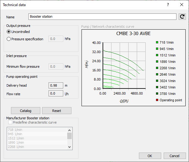
Details on Technical Data for Booster Stations
Information about the technical data dialog for booster stations.
If the minimum supply pressure of the water distribution company is not sufficient to supply all tapping points within the pipe network, a booster station has to be installed. The booster station includes a controller to keep the initial pressure in both static and flow pressure cases constant. As a consequence, there are three pressure ranges in the pipe network: from the network start onwards, from a pressure closed-loop controller onwards, and from the booster station onwards. For all section parts static pressures and flow pressures are available and can be displayed via data visualization. An additional printout for booster stations is available which gives out the operating point (Q.H), the temperature and the NPSH value of the system (Net Positive Suction Head in meters).
It is recommended to analyze the zonal structure of the pressure conditions before constructing the actual pipe network in order to define which areas have to be provided with a booster station and which areas are located in a standard pressure zone where a booster station is not necessary. Both areas should be separated in the pipe network.
If a booster station is only inserted into the hot or cold water partial network, the consumers connected downstream will be in different pressure zones. This can lead to significant temperature fluctuations at the discharge taps.
You are here:

Name
Specifies the name of the component. You can modify the name. Clicking  restores the default setting.
Output pressure
At first the booster station is calculated with the status uncontrolled. It acts passively in the pipe network without effects on the pipe network.. Switch to Pressure specification and enter the output pressure that is supposed to adjust itself downstream of the booster station.
Inlet pressure
Enter the minimum flow pressure (i.e. the required pressure at the inlet of the booster station) in the inlet pressure section.
Pump operating point
For neutral pumps the delivery height and the flow rate are calculated and then displayed.
Catalog, Reset
Catalog: Select a booster station from the manufacturer’s catalog. This option is not available in all program versions. Further, it depends on the installed product data sets which manufacturers and booster stations are available.
Reset: You may use this button to reset the values to a neutral booster station.
Manufacturer Booster station
Predefine characteristic curve: If several characteristic curves are available for a booster station, you may select a particular curve when the Predefine characteristic curve checkbox is set active. Else, the program will select the most favorable characteristic curve.
Pumps and Network characteristic curve
The displayed diagram will feature the pump and the network characteristic curve.