Creating a Feed Pipe Zones
Shows step-by-step how to create feed pipe zones.
Before you begin
To ensure that the network is calculated as accurately as possible, the feed pipes of all circuits should be laid out in order to take into account the pressure losses and capacity losses caused by the feed pipes.
Requirement:
You have already designed the circuit to which you would like to connect the feed pipe.
Navigate to:
Applies to: Panel heating, Panel cooling
Procedure
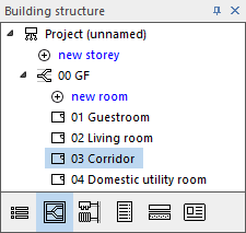
- In the Building structure, select the room in which you would like to create the feed pipe.
- Click Dimensioning new heating/cooling circuits
 and select Feed pipe in the context menu. Tip:
Alternatively, you can also click in an empty line of the table or press F5 in the table to open the context menu.
The New feed pipe dialog opens.
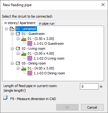
- Select the circuit to which you would like to connect the feed pipe.
- Enter the actual length of the feed pipe in the current room and confirm with OK.
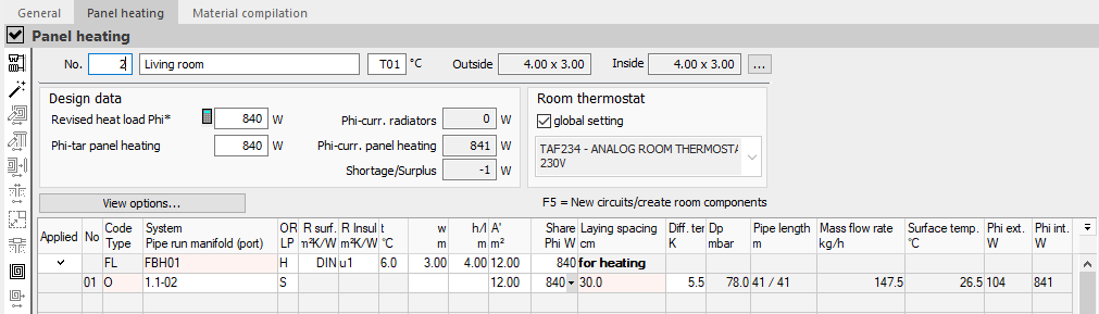
Results
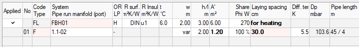
In connection with the desired pipe spacing, the required area and the return water pipe are set and the feed pipe zone will be displayed in the Code Type column of the table with the entry F.
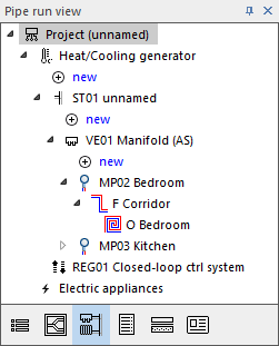
In the pipe run view, the feed pipe between the manifold connection and the heating circuit is displayed.
What to do next
For feed pipes with additional insulation on top and other coverings, you can consider the reduced power loss as a package by entering a percentage value in the Portion Phi W column.