Technical Data for Pumps
Information on the technical data dialog for pumps.
A pump is inserted into an existing pipe. The pipe is automatically cut and the pump connected. Installing a pump in a pipe network is a pressure recovery for pressure loss calculation. Pressure recovery is calculated based on the selected delivery head.
Installed pumps in your heating pipe network are initially neutral. The flow rate results from the mass flow rates of consumers.
You are here:
Name
Specifies the name of the component. You can modify the name. Clicking  restores the default setting.
Neutral Circulating Pump
In this section, you may specify component specific settings for a neutral circulating pump. The delivery head is either calculated from pressure losses of the system or entered manually. If you enter the delivery head manually, the volume flow rate of the system remains equal and all valves are set such that they create a higher pressure loss to achieve equal flow rates.
Calculate delivery head: You can let the program calculate delivery head. The pair of values that are volume flow rate and pressure loss are used to dimension the circulating pump.
If Calculate delivery head is activated, input fields delivery head and flow rate are deactivated and required values are shown. They are also later shown in printouts. Delivery head is calculated from the pressure loss of the pipe network.
If Calculate delivery head is deactivated, enter the delivery head of the pump in meters. Delivery head and flow rate (volume flow rate) are also shown in printouts.
Manufacturer Circulating pump
In this section you may select and dimension a manufacturer specific pump.
Catalog Opens the Pump selection dialog. Here, different models from various manufacturers are available. You may select a pump and assign the data to a pump in the model.
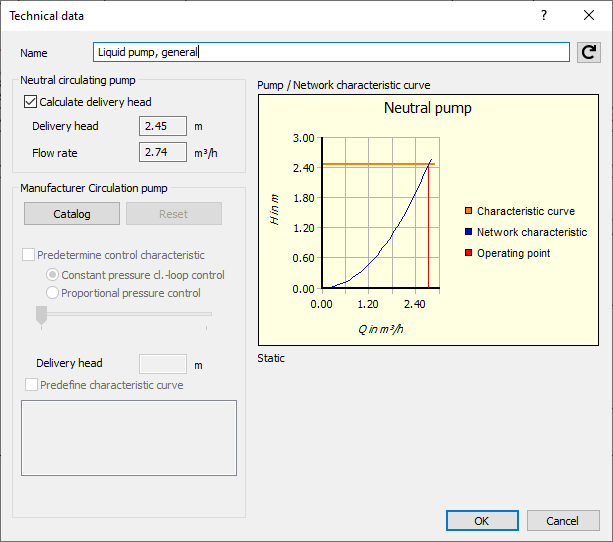
As soon as a manufacturer pump has been assigned, the operating point, the network characteristic curve and the pump characteristic curve are shown in the diagram. If more than one static pump characteristic curves exist, you can select one.
Reset: When resetting a pump, it returns to being neutral. A manufacturer is not cited. The delivery head is either calculated from pressure losses of the system or entered manually. If you enter the delivery head manually, the volume flow rate of the system remains equal and all valves are set such that they create a higher pressure loss to achieve equal flow rates.
Predefine characteristic curve: If the pump has a characteristic curve, you can specify the settings yourself. With the option Predefine characteristic curve activated, you have the option to change the characteristic curve by using the slider. Depending on availability, you can instantiate constant pressure cl.-loop control or proportional pressure control. The setting of the slider is mirrored in the input field delivery head. In the input field delivery head, you may enter the delivery head manually. Settings in the input field are mirrored by the slider.
For pumps connected directly behind each other, delivery head for one pump must be entered manually. The second pump is then by the program assigned sufficient differential pressure to overcome the system resistance.