Drawing Hydraulic Circuits
Shows step-by-step how to draw a hydraulic circuit.
Before you begin
You want to draw a hydraulic circuit in your pipe network.
Requirements:
You have already drawn in the supply and return pipes.
The installation of the hydraulic circuit is shown here using the example of a mixing circuit.
Navigate to:
Procedure
- Click on the button Hydraulic circuits ....
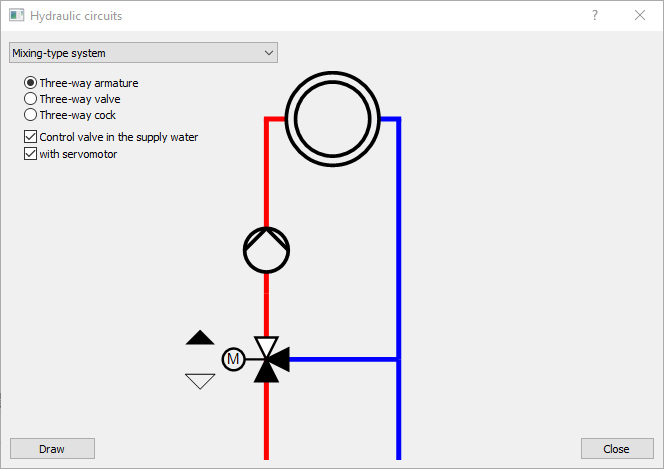
The dialog Hydraulic circuits opens.

- Use the drop-down list to select the desired circuit, e.g. a Mixing circuit.
- Use the radio buttons to select whether a three-way control valve, a three-way valve or a three-way stopcock should be used.
- Select whether the control valve should be installed on the supply. Note:
Depending on the selected circuit type, you can insert additional components (actuator for the mixing valve, throttle valve for constant admixture, backflow preventer for injection circuit, etc.).
- Optional: Press the arrow buttons
 /
/ to display the function of the selected circuit. Note: The mass flow is displayed in percent and the temperature change of the lines is shown in color.
 - Click the Draw button and follow the instructions in the command line. Note: The drawing process depends on which circuit and which additional components have been selected.
- Select the insertion point for the mixing valve in the supply or return pipe. Note: Check for information in the command line. The rotation of the mixing valve is corrected automatically.

- On the return pipe, select the point at which the bypass pipe to the mixing valve should start. Note:
If the mixing valve has been drawn on the return pipe, the connection point of the bypass pipe is selected on the supply pipe.
The bypass pipe and the T-piece are inserted automatically. The rotation of the mixing valve is corrected if necessary because the position of the bypass pipe has now been defined.

- Select an insertion point for the pump downstream of the mixing valve in the direction of flow.

Results
