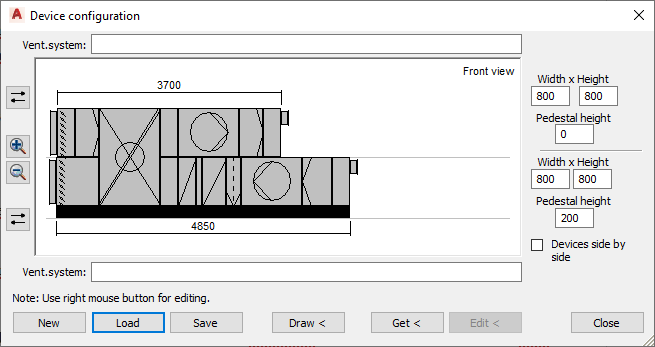
Details on Device Configuration
Information about the dialog Device configuration in the section 3D Air Duct.
In this dialog you can design central air handling units in one or two planes and then have them drawn automatically with previously defined connections.
You are here:

System
Enter a name of your choice for the central device in this field.
Preview
In the preview window you can see a schematic representation of the device. Do a right click in the viewport after entering a height for the lower device to create the first component in the lower plane. You can then use the context menu to copy, delete and edit components.
 Reverse air direction
With these buttons you can change the air direction of the upper and lower plane individually.
 Zoom in,
  Zoom out
With these buttons you can zoom in and out in the viewport. Alternatively, you can use the mouse wheel when the viewport is selected.
Width/ Height/ Pedestal height
Enter the dimensions for the respective level of the central device in the fields. Before components can be created, the dimensions of the device must be determined.
Devices side by side
Activated: The devices are not placed on top of each other, but side by side. The viewport then shows a view from above instead of the front view of the device..
New
Deletes the current device configuration so you can configure a new central device. If you haven’t yet saved a device, you will be asked if you want to save your device compilation before deleting it.
Load
Allows you to load central air handling units that have already been saved.
Save
Allows you to save central air handling units in xml format.
Draw <
Allows you to draw in the central air handling unit. Check the current construction height before drawing the ventilation device.
Get <, Edit <
You can use the button Get < to pick the data of a drawn ventilation device and display it in the device configurator. The individual components can then be edited. Edited device configurations can be transferred to drawn devices using the Edit < button.