Source graphic for image montage: © Buch&Bee – stock.adobe.com
For many years, LINEAR has offered an almost complete solution for the design and calculation of MEP systems. The main focus to date has always been on the trades related to air and water. Accompanying features, such as the numerous user-friendly functionalities for designing with Revit and the strong support for BIM-compliant design processes, increasingly caught the interest of those whose specializations were not previously supported in LINEAR Solutions. Particularly in integrated or general design offices, where the staff responsible for the various trades work more closely together, teams using our LINEAR Desktop were increasingly eyed with interest by the designers responsible for the electrical trade. As a result, we were increasingly asked for the integration of corresponding workflows for electrical systems as well.
With version 24.3, which was released in July, we have fulfilled this request and for the first time introduced LINEAR Desktop Electrical for Autodesk Revit. As in any other of our Desktop applications, we have of course also integrated the various basic features. In addition, Desktop Electrical offers specific tools that make it easy to position electrical components, such as switches, sockets and cable routes. For the calculation of electrical systems, we have intensified the cooperation between LINEAR and ETAP (formerly Alpi) so that the models created with Desktop Electrical can be calculated seamlessly with ETAP Caneco.
Version 24.3 marks just the beginning in terms of designing electrical systems. However, below we would like to take a closer look at what is already possible with this release.
What does it include?
As already mentioned, the products in our Desktop family offer a wide range of useful functions that provide support throughout the entire design process. Examples include the use of the Control Board with convenient view control and View management as well as the quick and easy creation of sectional views or a 3D selection frame. These are features that users probably already take for granted in their everyday use of LINEAR. However, in consultation with electrical engineering experts, it quickly became clear that such features were completely missing from their daily work. If we now roughly map out a design process using the tools available in the LINEAR Desktop, we can see that the first release version already covers a large number of design phases with features from Desktop Electrical. We will now take a closer look at some of these features.
Pre-conception design
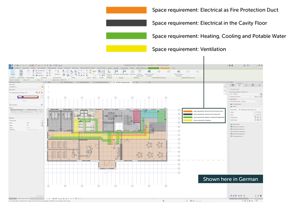
Let’s start in the early design stages: Space requirements for cable ducts and large components such as in equipment rooms must be defined and coordinated. With the pre-conception design workflow, we offer a feature with which outlines of pipe and cable routes can be communicated to others involved in the design process in form of placeholders. In case narrow passages are identified, cross-sections for pipe and cable routes can already be fully specified. This makes it possible to determine whether the available space is sufficient or whether more space is required for technology in central locations at an early stage.
Even at this stage, you can assign suitable service types to the cable trays in detailed cross-sections. When transitioning to the next design phase, individual cable trays can be automatically generated from the cable routing elements. The cable routing can thus be easily refined without having to model the entire route a second time.
Service types
Service types are required, for example, to facilitate the corresponding routing in the calculation using Caneco. When using the LINEAR service type management, the name of the storey in which the cable tray is located is automatically added to the service types of the cable trays. This ensures the correct allocation between switchgear, appliances and cable route for the calculation.
Coordination with other trades
The aim of good design is to meet all requirements for the construction of a building from different perspectives in the best way possible. This often results in conflicting goals that need to be resolved. Many constructive problems can be solved through early coordination between the parties involved. The LINEAR Desktop provides many helpful features for this, which are increasingly being used for draft and execution planning.
With the help of the LINEAR Collision Check, all trades or systems can be checked for collisions. This can also take into account damages to operating and assembly areas. Collisions that frequently occur, e.g. between heating pipes and electrical cable routes, can then simply be resolved with the “Cable Offset” command by routing the cable tray around the heating pipes.
Further collisions of course occur each time the building structure and pipes or cables overlap. If statically relevant, these must at least be approved by the structural engineers and architects responsible for the building. For this purpose, we offer an integrated workflow with our slot and opening design. Provisions for voids can be used to automatically create opening proposals and then communicate them using the open BCF standard (BIM Collaboration Format). The receiving party does not have to be using any LINEAR Desktop. The free LINEAR Void Manager can be used to import the suggestions into the model and either accept or reject them. This classification, including any comments on rejected openings, is then fed back to the relevant specialist design team via BCF. If necessary, the cable routing is corrected and the adapted opening proposals enter a new coordination loop.
The Desktop area “Issues and Tasks” supports you in managing all messages relating to openings or from other LINEAR modules such as the collision check, the model check or the calculations. Here, all topics requiring coordination can be managed in one place and integrated into the model.
Library
On the Library tab you can easily manage and use all your Revit families. In addition to the standard LINEAR content, you can also seamlessly integrate your own content by structuring it into disciplines, projects and locations.
With the V24.3, a selection of neutral surface-mounted and flush-mounted installation devices is supplied with the Desktop Electrical. These are automatically placed in a flush-mounted frame during individual placement. Our new frame and line configurators offer significant time saving when placing multiple components.
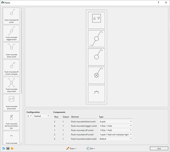
Frame Configurator
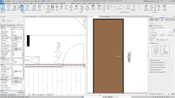
With the frame configurator, you can put together combinations of switches, sockets, thermostats, etc. simply by drag-and-drop and place them directly in the desired position in the model. They can also be easily installed in window reveals. For the floor plan view, the corresponding symbols are directly displayed correctly stacked. This completely eliminates the need to readjust distances or place symbols separately.
Installation Line Configurator
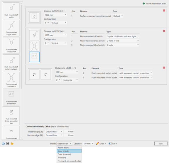
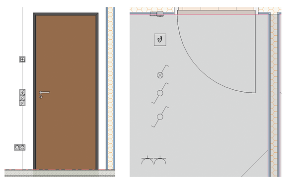
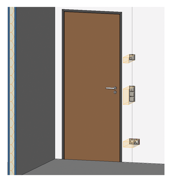
In the configurator for installation lines, you can also combine installation devices using drag-and-drop. In this configurator, however, entire installation lines between floor and ceiling are defined with different heights. For example, this makes it easy to put together classic combinations with three installation levels next to doors.
- 1,500 mm Room Thermostat
- 1,050 mm Combination of 3 switches
- 300 mm 2-way socket, horizontally aligned
The standard-compliant reference point for the placement height of the frame is automatically taken into account. With the selected placement mode ‘Door (inside)’, a door can now simply be selected and positioned. To do this, the installation line is placed on the room side opposite the door hinge at the set distance from the frame. If the set distance needs to be amended afterwards, the placed installation line can easily be moved along the wall surface.
For greater flexibility in placement, the configurator offers several additional placement modes, e.g. ’Door (exterior)’, or manual placements on the nearest edge. A particularly efficient approach is provided by the ‘Room-Doors’ mode, which automates the placement of identical installation lines multiple times. For example, let's assume that the previously set configuration is to be used in every office along a long corridor. By simply selecting the relevant MEP rooms in the model, an installation line is automatically placed next to the door in each room, taking into account the set distance.
The command “Working Section in Front of Wall” is ideal for checking the result visually. Simply select a wall side and a working section is created which extends to the adjacent walls and has a cutting depth up to the back of the wall. Simple and fast.
Classification according to IFC and cost groups
The LINEAR Classification can be used to assign classification parameters to components and model elements. Like that, the IFC classification for a complete model can be carried out easily, which significantly improves the semantic quality of an IFC export. Cost groups are another example of classification systems. For the preparation of cost estimates and calculations, such structuring can significantly increase the quality of the cost calculation with very little effort. The cost group is written to the components contained in the model as a shared parameter, which can then be used for component lists.
Element classes and property sets
With the help of element classes and property sets, the LINEAR Desktop offers a powerful tool for managing data in the model and storing the structures and formats required for the subsequent processes. The intuitive configurator not only allows you to set up rules for permitted values and data formats, but also to configure your own “LINEAR Properties Window” for existing or freely definable element classes. That way, only data that is currently relevant to you remains visible. This means you no longer have to tediously search through the Revit Properties. In the background, the LINEAR Desktop supports you in delivering high data quality by pointing out errors such as incorrect formats, value ranges or missing data as soon as they are entered.
Since version 24.3, every LINEAR Desktop now also offers the option of defining a information levels. Depending on the current design phase, you can only display attributes relevant at the time. Especially in the context of “Building Information Modeling”, this feature supports a range of possibilities to increase or ensure the data quality in the model phase by phase.
Construction design
If the project has already progressed so far that the positioning and dimensioning of the cable routes and cable ladders has been completed, these can be divided into section and delivery lengths, for example to assign unique item numbers. The LINEAR Desktop also offers easy-to-use functions for this purpose.
The mounting of cable routes can also be planned here. Simply select the routes to be mounted and the load-bearing component. With just a few clicks, the cable routes can be suspended from a ceiling at a set distance, e.g. with insertion rails and threaded rods.
Conclusion
With the Desktop Electrical, we have entered a new area of Revit design. Considering the multitude of features that open up new possibilities for electrical designs when modeling in Revit, we are confident that this solution will significantly increase productivity when working on a model. From design to model checks, features for ensuring data quality to construction design, the scope of Desktop Electrical covers a great deal even in this first version. And there are many more ideas on our agenda.
We are pleased to have taken this step so that we can now cover all trades, including electrical, with an integrated software package. This new option will certainly help you with your project work.
We are looking forward to your feedback!
Would you like to read more articles like this? Vote for them (anonymously) here.
