Extending a Scheme with Pipes and Symbols
Shows step-by-step how to manually draw pipes and insert symbols in an existing scheme.
Before you begin
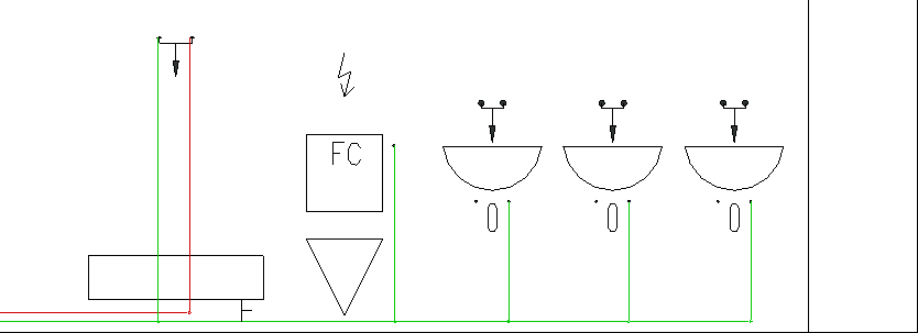
You have created a scheme and want to add and connect components that were added later.
Navigate to:
Applies to: Scheme.
Procedure
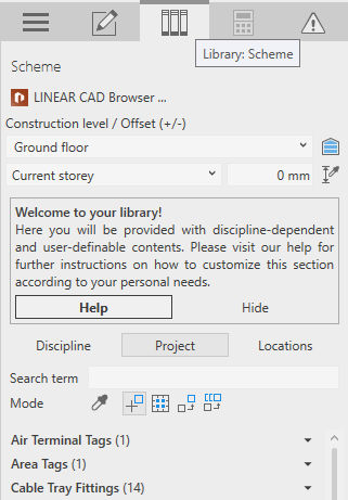
- Click on Discipline to display all symbols of the current discipline.
- Enter a Search term and select the corresponding symbol from the results. The family of components is loaded.
- Click the symbol again to place it in the scheme. The symbol hangs on the cursor.
- Place the symbol in the desired position and then switch to the Construction tab.
- Open the section Draw pipe.
- Select the a corresponding System class and specify the Fitting diameter.
- Click Draw pipe < and draw the required pipes. Tip: After clicking Draw pipe <, activate the Revit option Chain to be able to draw continuously.
Results
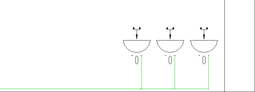
The added components are added to the scheme with their symbols and required pipes.