Details about the Construction Tab for the Scheme Workflow
Information about the construction tab for the workflow Scheme.
You are here:
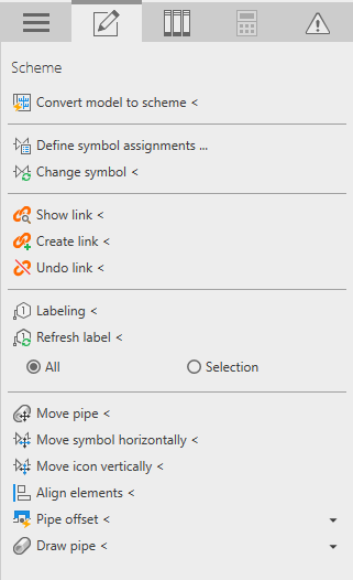
Derive scheme from model
Derive scheme from model <
Starts the function for deriving the scheme from the model. After clicking on an element of the network, the Derive scheme from model dialog opens where you can make settings for the scheme.
Symbols
Define symbol assignments ...
Opens the Symbol Settings dialog, where you have the possibility to change symbols for components in the scheme or to reset them to the default assignment.
Change symbol <
Changes an existing symbol assignment in the scheme.
Links
Show link <
Starts the function for selecting an element with subsequent display of the respective linked element. The selection can be made in the model as well as in the scheme.
Create link <, Detach link <
Creates or detaches the link of elements between model and scheme.
Labeling
When labeling manually, the assigned labels of the dialog Symbol settings are used.
Labeling <
Starts the function for labeling elements in the scheme.
Update labels <
Updates All labels or only those of the selection in the current scheme.
Edit scheme
This area provides functions to align and adjust the position of pipes and symbols.
Move pipe <: Moves a pipe orthogonally to its course. Any connected pipes are also moved. While moving the pipe, a live preview is displayed. To prevent an accidental change of the network topology, pipes can only be moved within their segment. A segment is limited by fittings or built-in parts.
Move symbol horizontally </Move symbol vertically <:
After clicking on the desired function and selecting symbols to be moved, a live preview is displayed at the cursor. To prevent an accidental change of the network topology, symbols can only be moved within their segment. A segment is limited by fittings or built-in parts. Built-in parts can only be moved along their pipe.
Connect symbol <: Connects symbols to pipes in a scheme. The command offers the Loop-through option for connecting potable water consumers. You can set the corresponding dimensions for the connection using the Width ear elbow, Fitting diameter and Distance pipe fields.
Align elements <: Aligns elements to a user-defined reference line. The reference line can be aligned to any elements in the scheme and is displayed as a dashed line after clicking on it. In the second step, the line of the symbol to be moved can be clicked to move the symbol. If the reference line is not parallel to the selected line of the symbol to be moved, the symbol will be moved to the intersection of the click point and the reference line. If the alignment would result in a changed network topology, the symbol is only moved within the constructive possibilities.
Pipe offset
Pipe offset <
Starts the function to create pipe offsets in the scheme considering the settings.
Radius
Text field for entering the pipe offset radius in mm.
Alignment
Clicking on the buttons changes the horizontal or vertical orientation of the offset.
Update <: Applies the current radius and alignment settings to selected offsets. If no offsets are selected, they can be selected after clicking Update <. The function filters the selected offsets.
Draw pipe
Draw pipe <
Starts the construction command for new pipes in the scheme with the selected System class. After clicking Draw pipe <, activate the Revit checkbox Continuous at the top left below the Revit ribbon for continuous drawing. After terminating the command with Esc, fitting circles with the specified fitting diameter are automatically placed at bends and T-pieces.
If you select built-in parts or fittings and delete them with the Del key, the resulting gap of the respective pipe will be closed automatically.