Details on Derive Scheme from Model
Information about the dialog Derive scheme from model in connection with the Scheme workflow.
This dialog appears after clicking Derive scheme from model < on the Construction tab and selecting a component in the model.
You are here:
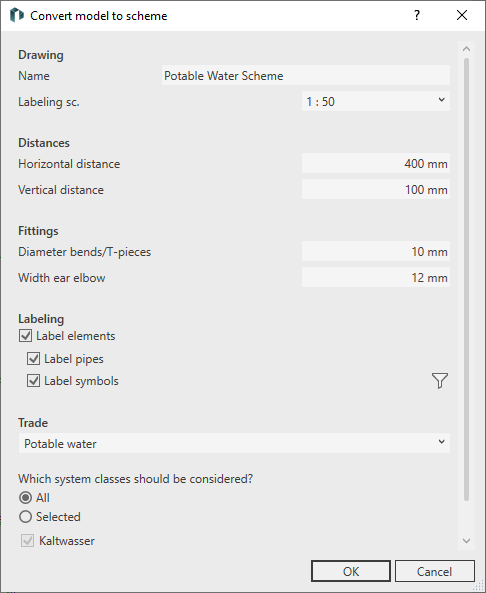
Drawing
Name
Freely defined name for the new scheme. The scheme will be saved under this name in the drawing views.
Scale
Drop-down list for selecting the scale. The scale affects the rendering of labels and dimensions in the scheme and can be adjusted subsequently.
Spacing
Horizontal spacing
Horizontal spacing between symbols of consumers or vertical pipes.
Vertical spacing
Vertical spacing between horizontal parallel pipes.
Fittings
Diameter bends/T-pieces
Diameter with which the symbols for bends and T-pieces are to be displayed in the scheme.
Width ear elbow
Distance between the pipes when the ear elbows are connected. You can enter values ≥ 12mm.
Labeling
Label elements - enabled: The elements in the diagram are automatically labeled according to the selection of Label pipes and/or Label symbols. If you select the Label symbols option, you can use the checkboxes in the Activate components dialog to select which component symbols are to be labelled.
 : Opens the Activate components dialog in which you can select which groups and variants of component symbols are automatically labelled when the schema is created. The prerequisite is that the specified parameters have been created in the components after the model has been calculated ().
Trade
Selection of the discipline and the associated system classes for the creation of a scheme.