Details on Provisions
Information on the Provisions section.
You are here:

Provisions <
Positions void proposals and slots in the model. You can place void proposals manually and semi-automatically in this section. You can place slots manually in the model by defining the width, depth and length before positioning, or by defining the width and depth in advance and specifying the length using two points in the model.
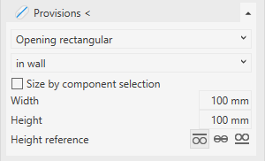
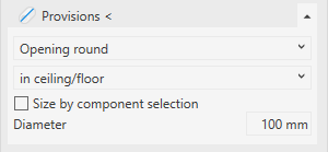
Drop-down list Void type
You can choose between slots and rectangular or round openings.
Drop-down list Positioning
Void proposals can be placed in vertical surfaces such as walls, columns and horizontal surfaces such as ceilings, joists or roofs.
Slots can be placed in vertical surfaces such as walls or columns and in horizontal surfaces such as ceilings or floors.
Size by component selection
The status of this checkbox determines the mode of placement for voids.
| Activated: semi-automatic positioning | Deactivated: manual positioning |
|---|---|
| Lateral distance: The distance between the pipe or duct and the inner edge of the opening. Note: The setting Round up placeholder dimensions in the Options dialog () results in the lateral distances generated in the model being larger than the lateral distance specified here, because the calculated dimensions of the breakthrough proposal have been rounded up according to the setting. This applies to all placeholders where lateral spaces are specified. | Breakthrough dimensions: Enter the dimensions of the void. The depth of a void is determined by the selection of the wall to be broken through. |
| Height reference : Only applicable in floor plan and when placement inside the wall is available. You can align the void proposal to be placed at the top edge, center, or bottom edge. The construction height results from your specifications in the construction level / offset (+/-) section. If a placeholder is placed manually in a 3D view, the construction height is not taken into account and you have to place the placeholder yourself. |
fixed length
The status of this checkbox determines the mode of positioning for slots.
Enabled: Enter the width, depth and length of the slot and place the slot with one click in the model.
Disabled: Enter the width and depth of the slot and set the start and end points in the model. This 2-point method can be used in floor plan, building and section views.