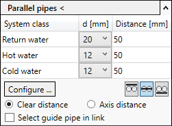
Details on Parallel Pipes
Information on the parallel pipes section.
If you have already designed a pipe run, you can add additional pipes in parallel.
You are here:
Applies to: heating, potable water, waste water, ventilation, cooling, gas, fire protection.

Parallel pipes <
Adds further parallel pipes to already designed pipe runs.
Table
The table shows the pipes that are added with Parallel pipes <. The order of the pipes can be changed by drag and drop. In order to change the configuration, click Configure....
| System class | d [mm] | Distance [mm] |
|---|---|---|
| Indicates the system class of the pipe being added. In order to change the system class, click Configure.... | Change the diameter of the pipe being added. | Change the distance to the pipe in the row above. |
Configure...
Opens the Set parallel pipes dialog. Here you configure the pipes that are added to the existing pipe run in a table.
 Justify to
Defines the reference edge of the pipes to each other.
| Justify to the top | Justify to the center | Justify to the bottom |
|---|---|---|
 |  |  |
Clear distance or axis distance
Clear distance: The value entered under Distance refers to the distance between the outer edges of the adjacent pipes.
Axis distance: The value entered under Distance refers to the distance between the axis of the adjacent pipes.
Select guide pipe in link
If the pipe run to which the parallel pipes are to be added is in a link, activate this check box. You then select the pipe run to be added from the link. The new parallel pipes are constructed in the current model.