Details on Technical Data for Lifting Stations
Information about the technical data dialog for lifting stations.
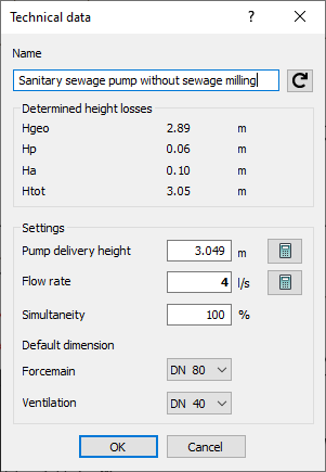
The term lifting station covers all installation objects that cause a flow rate within the drainage network by means of a pressure pipe, for example, sanitary sewage pumps. A lifting station has three connection points (supply, pressure pipe, ventilation).
You are here:

Name
Specifies the name of the component. You can modify the name. Clicking  restores the default setting.
Determined height losses
As soon as the pipe network is calculated, the values Hgeo, Hr, Ha, and Htot will be displayed in the Determined height losses section.
Settings
Pump delivery height, Flow rate, Simultaneity
Values for pump delivery height, flow rate, and simultaneity may be entered here. Using the button  for the Pump delivery height you may take over the calculated value for the total delivery height Htot as the delivery height of pump. By clicking
  for Flow rate you can take over the input flow rate from the calculated data. When using a manufacturer pump, enter the respective values manually.
Default dimension
Forcemain
You may optionally set or measure the Default dimension of the Forcemain. If you select the setting free, the forcemain will be dimensioned automatically. Material and changes in dimension are also possible in the forcemains of lifting stations. The sections parts will be detected as shafts or forcemains up to the next branch.
Ventilation
Set a dimension for the ventilation duct. If this particular nominal diameter is not available in the pipes table, the next higher dimension will be used automatically.