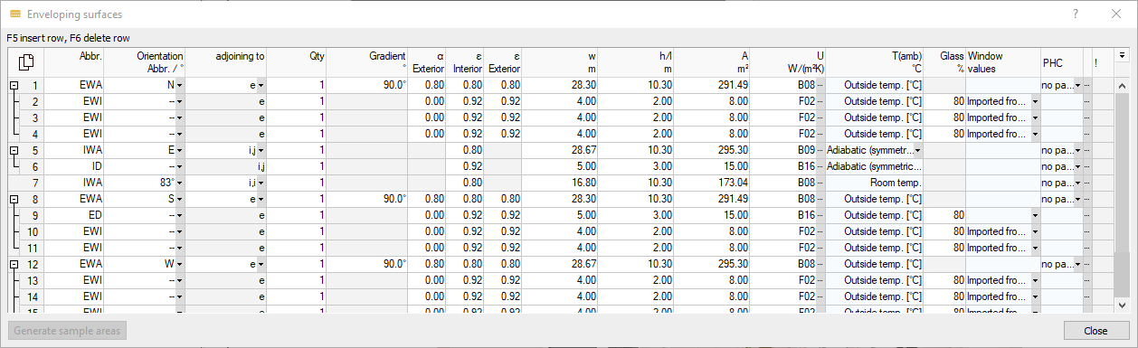
Details on enveloping surfaces
Information on the enveloping surface dialog in the dynamic cooling load calculation.
The enveloping surfaces should be recorded as completely as possible in order to take into account all such building masses that contribute to the exchange of thermal radiation.
You are here:
Table
By clicking  you have the possibility to copy the contents of the table with or without column heading and paste it into Excel.
If you have selected individual rows or cells, you can copy the selected data with the key combinations Ctrl+C (with column heading) or Ctrl+Shift+C (without column heading) and paste it into Excel, for example.
Abbr.
Abbreviation for the component. You can use the known LINEAR Building abbreviations:
-
EWA: Exterior wall
-
EWI: Exterior windows
-
ED: Exterior doors
-
RF: Roof
-
RW: Roof window
-
CL: Ceiling
-
FL: Floors (also in contact with ground)
-
IWA: Interior walls
-
IWI: Interior windows
-
ID: Interior doors
-
DAR: Deduction areas
Direction abbr. /°
The cardinal direction of the respective component. The cardinal direction can be selected from the drop-down list or specified in degrees.
adjoining to
Indication of the thermal conditions on the other side of the component. Possible inputs:
| Code | Meaning | Possible for these components |
|---|---|---|
| e | external: adjoining to outside air | EWA, EWI, ED, RF, RW, FL |
| g | ground: adjoining to ground | EWA, FL |
| i, j | Adjoining heated adjacent rooms | IWA, IWI, ID, CL, FL |
| i,i | Area adjoins this room on both sides (e.g. room divider) | IWA, IWI, ID, CL, FL |
Qty.
Quantity of a component that exists. If there are several identical components, you can enter the number here.
Inclination °
Inclination of the component relative to the ground. The inclination influences the diffuse and direct radiation on the component.
α outside
The absorption coefficient describes the absorption capacity of opaque exterior components for short-wave solar radiation. For windows and other transparent exterior components, the value is 0. For external walls, the value 0.80 is suggested by default.
ε inside
The emission coefficient for long-wave radiation describes the ability of the side facing the room to absorb and emit long-wave radiation. The coefficient determines the proportion to which the component participates in the exchange of long-wave radiation. For windows, the suggested value is 0.92. For walls, ceilings and floors the value 0.80 is suggested.
ε outside
The emission coefficient for long-wave radiation describes the ability of exterior surfaces and exterior components to absorb and re-emit long-wave radiation from the environment. For windows, the suggested value is 0.92. For exterior walls, the value 0.80 is used by default.
W - (max.) Width, h/l - (max.) Height or (max.) Length, A - Area, A’ - Net area:
When creating building structures in LINEAR Building:
In these four columns, you define the width, height, length or surface area of the enveloping surfaces. If the width and height or length is entered, the surface area is calculated from the data. If the area is entered, the entries for width, height or length are deleted. In column A’ the area minus all deduction areas is displayed.
In these fields it is possible to enter dimensions as a term. Enter the term e.g. with 2.25+1.35 and press Enter. The result is calculated and entered. For areas that are to be only partially included in the calculation, such as gable walls, the dimensions can be entered with an appropriate factor (e.g. 0.5*width*height for triangular areas).
When transferring building models from Revit and AutoCAD:
For AutoCAD building models that are not based on a linked IFC architecture (3D - IFC link workflow), the values for b and h/l are not output if their product is not equal to the area A.
If your project is based on a building model that was detected from Revit or was created from AutoCAD and is based on a linked IFC architecture, the maximum dimensions determined from the model according to the corresponding standard are always output in the two columns b and h/l, even if the product of b and h/l does not correspond to the area A calculated according to the standard.
In the column A’ the surface area minus all deduction areas is displayed.
U W/(m2K)
The U-value can be entered directly as a numerical value for windows and interior doors, as these are particularly lightweight components with low mass and heat capacity. For all other components, the exact layer structure is required with details on density, thermal conductivity, lambda and specific heat capacity.
T(amb) °C
The ambient temperature for the respective component. For outside walls, the outside temperature is automatically entered from the climate data.
Adiabat
For interior walls, Adiabat (symmetrically loaded) is automatically suggested. The assumption is that the radiation and the heat flow of the side facing away from the room correspond to those of the inside. The wall radiates in equal parts into the room and into the adjacent room.
Adiabat (reverse side): The assumption is that the back of the wall is ideally insulated and that there is no exchange of heat with the neighboring room.
Temperature specification: You can enter a constant temperature manually.
The VDI core combines similar components for the calculation. Therefore, for rooms with only interior walls, a constant temperature (for the reverse side) must be specified for at least one wall so that the core has a reference against which an exchange can take place.
General temperature profile set: You can also assign a general temperature profile set to a component, or select a different profile or create a new one by clicking Add/Change. The effects of radiation on the inside of the wall are assumed for the back of the wall and mirrored, as with Adiabat (symmetrically loaded).
Glass %
Glass area in percent. Here only the glass area is meant, i.e. window area minus the frame area.
Window values: The assigned window configuration. From the drop-down list you can assign existing configurations, or click Add/Modify to create a new configuration or modify an existing one.
Surface heating/cooling: Drop-down list to select the surface temperature control for this component. Clicking Adjust options ... opens the Component properties for surface temperature control dialog, where you can adjust settings for the dimensioning of surface temperature control.
Show or hide columns  : opens a list where you can show or hide columns of the table.
Generate sample surfaces
If you do not yet have any concrete information on the enveloping surfaces, you can have standard surfaces generated automatically in order to make initial rough estimates.