Configuring and Placing an Installation Line
Shows step-by-step how to configure an installation line and place it in your project.
Before you begin
You want to configure a group of switch frames and place them in selected MEP spaces.
Requirements:
The current view is the one in which the installation line is to be placed.
Navigate to:
Applies to Electrical.
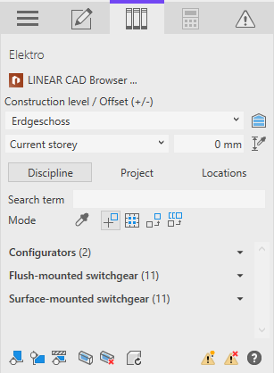
Procedure
- In the Configurators area, click on Installation line ... to open the configurator for installation lines.
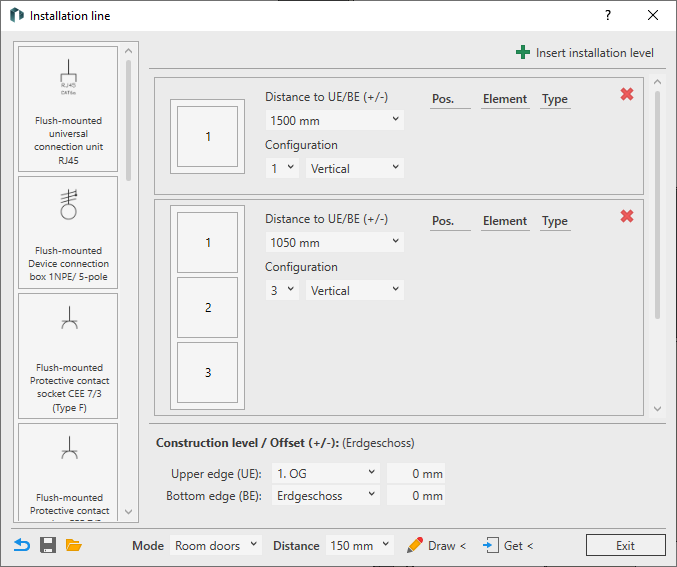
- In the Construction level / Offset (+/-) area, select the reference level for the upper and bottom edge; enter an offset if required.
- Create the desired number of installation levels by clicking on
 Add installation levels or by clicking on
  Delete existing levels.
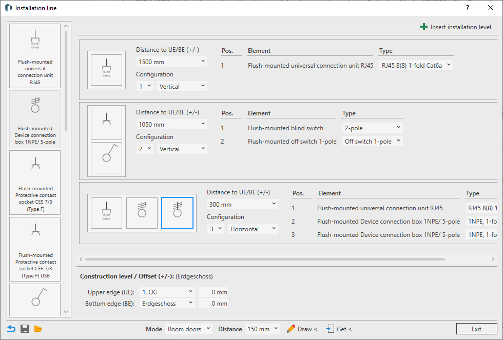
 - Select the number of positions and the alignment for each installation level in the Configuration area for each switch frame.
- Enter the Distance to UE/BE (+/-) for each installation level.
- Drag and drop the required components from the component library to their positions.
- Check and change the Type for your components if necessary.
- Select a Mode in the footer and enter the horizontal Distance to reference edges. This topic describes the placement in Room doors mode. Further information on placement modes can be found on the help page for the dialog.
- Click Draw <.
- Select all MEP spaces in which the configuration is to be placed and confirm the selection with Enter.
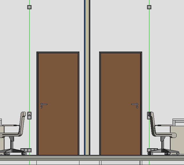
Results
The configuration is placed next to the doors of all selected MEP spaces with the settings made.