Details on Installation Line
Information on the dialog Installation line.
You are here:
Component library
Gallery of all available components for equipping the switches. Individual components can be dragged and dropped to the desired position.
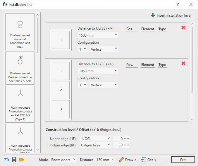
Installation level
An installation level is a switch group with up to five components. The components of an installation level can be arranged vertically or horizontally. You can define the Distance to BE/UE (+/-) for each installation level. A positive value shows the distance above the bottom edge, a negative value shows the distance below the upper edge. An installation level is displayed further up or down in the installation line according to the defined distance. You define the top or bottom edge in the Construction level / Offset (+/-) area.
Click on  Insert installation level to create a new installation level with the default settings: A vertically aligned switch frame with three positions, 500 mm above the bottom edge.
Click on  to delete the respective installation level.
The individual positions can be equipped with components from the component library using drag-and-drop. If a component from the component library is placed in a position that is already occupied, the existing component is replaced. Components can also be subsequently moved to a different position in the configuration using drag-and-drop. If there is already a component at the target position, the positions are swapped after dropping. A placed component can be copied to other positions in the configuration by holding down the Ctrl key and dragging and dropping. If the target position is already occupied, the existing component is replaced with the copied component. A component that is not required can be selected and removed from the configuration using the Del key. As long as the configurator is open, any action can be undone with Ctrl + Z or restored with Ctrl + Y.
Construction level / Offset (+/-)
You can define the upper and bottom edge with an offset separately for each storey. All levels of the storey dialog are available for selection. The offset is calculated based on the height of the selected construction level. When drawing an installation line, the settings for the construction level with offset for the respective storey are saved in the dialog.
Footer
 Reset configuration to default values
Deletes all placed components of the installation line and sets the default configuration with three installation levels.
 Save configuration
Opens the file explorer in which you can save the current configuration in XML format.
 Load configuration
Opens the file explorer in which you can open a configuration in XML format for use in the project.
Mode
You can choose between different modes for the automatic placement of the installation line:
| Mode | Description |
|---|---|
| Room doors | At least one MEP space must be selected for placement. The configuration is placed in all selected MEP spaces at the specified Distance next to each door opposite the door stop. |
| Door (inside) | A door must be selected for placement. The configuration is placed opposite the door stop in the opening direction. Select all the desired doors one after the other and end the command with ESC. |
| Door (exterior) | A door must be selected for placement. The configuration is placed opposite the door stop in the opposite direction to the opening direction. Select all the desired doors one after the other and end the command with ESC. |
| Freehand | Allows you to select any points on walls to place the configuration. The specified Distance is ignored. |
| Freehand at nearest edge | Places the configuration with the specified Distance on the edge of the wall surface nearest to the click point. |
Distance: Drop-down list for selecting the distance at which the configuration is to be placed in relation to the respective reference element. You can also enter user-defined distances. This value is ignored in Freehand mode.
 Draw <
Switches to placement mode. Depending on the selected placement mode, select MEP spaces, doors or points on wall surfaces. After selecting the reference elements, the switch group is placed at all desired locations. Finish the process with ESC.
 Get <
Get <
Loads the settings of an already placed configuration after selecting it.