Details on Pipes in Drawing in the Settings for Heating and Cooling
Information about the section Pipes in the drawing in the dialog Settings for Analyse Heating or Analysis Cooling.
When setting up this section, keep in mind that a pipe network in the form of a pipe run scheme is only partially scalable at most. Edit the corresponding section directly in the calculation dialog to calculate the change in pipe lengths of a section part.
You are here:
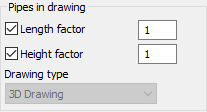
Lengths/Height factor
Enabled: The drawn pipe lengths and heights are determined during detection and multiplied by the entered factor. Since drawing is usually done at a scale of 1:1, the default factor is 1.
Disabled: For the first detection from the drawing, the length/height is considered to be zero for all sections. If you have already edited section part data in the calculation dialog, the user-defined values are used.
Drawing type
The drawing type is taken from the project settings and is only displayed here. The program derives the Z-axis for the determination of heights from the selected drawing type.