Details on Component Detection in the Settings Gas
Information about the component detection section in the Settings dialog in the Gas Pipe Network Calculation.
In this section, specify global settings for the detection of components, pipes and ducts that are to be considered during calculation.
You are here:
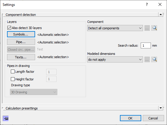
Layer
The layers are preset according the program specifications. The program recognizes different types of pipes, by the layer on which these pipes have been drawn.
Also detect 3D layers
Activated: 3D pipes from the Design 3D Pipe&Power module are also included in the calculation.
Disabled: 3D pipes from the Design 3D Pipe&Power module are not included in the calculation.
Symbols..., Pipe..., Closed circular pipe..., Texts...
Clicking one of the buttons in the layer selection opens the Select Layer dialog where you can manually specify on which layers the respective elements are located, if necessary.
Pipes in the drawing
When setting up this section, keep in mind that a pipe network in the form of a pipe run scheme is only partially scalable at most. Edit the corresponding section directly in the calculation dialog to calculate the change in pipe lengths of a section part.
Enabled: The drawn pipe lengths and heights are determined during detection and multiplied by the entered factor. Since drawing is usually done at a scale of 1:1, the default factor is 1.
Disabled: The drawn pipe lengths and heights are determined during detection. If you have already edited section part data in the calculation dialog, the user-defined values are used.
The Drawing type is taken from the project settings and is only displayed here. The program derives the Z-axis for the determination of heights from the selected drawing type.
Component selection:
Dropdown list with the options for component selection:
-
Detect all components: The entire pipe network with all components is detected and taken into account in the calculation.
-
Detect partial network: If you select the Detect partial network option, the dialog is minimized and you can select the desired partial network with the mouse in the current view. You can select or deselect the corresponding components individually with a selection frame or with the mouse pointer. Confirm the selection of the components with Enter. The number of detected components is displayed after selection.
If you start the calculation after selecting Detect partial network, the program asks you to reconfirm the selected components for the partial network. You have the possibility to change the selection of the components again or to start the calculation with the currently selected partial network by pressing the Enter key. An error-free calculation is only possible if the selected partial network is self-contained.
 : Allows to reselect a subnet in the current view. This button is only activated if you have selected the option Detect partial network and have already made a component selection.
 : Selects the selected partial network in the current view. This button is only active if you have selected the option Detect partial network and have already made a component selection.
Search radius
The search radius specifies up to which value distances between components, if any, created during drawing, are tolerated when calculating the network. This function prevents inaccuracies in the drawing of component connections in the millimeter range from being detected as open ends and thus as errors during the calculation.