Details on Technical Data for Pipes
Information about the component data dialog for pipes.
Pipes are always drawn as lines in the drawing. The program recognizes the pipe type (Waste water or Ventilation) by the layer on which these pipes are located. A pipe may be connected at each end to a maximum of three other pipes (crossing T-piece) or to one block, which symbolizes another component. It is neither possible to connect several pipes to a component connection nor to leave pipe ends open. The pipe type is either determined by the default settings which you can specify in the Pipe tables or by the separate definition of the pipe.
You are here:
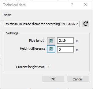
Name
Shows the name of the component. You cannot modify the name.
Settings
Pipe length: You can change the pipe length manually or reset it to the drawn length by clicking  .
.
Height difference: The value displayed here equals the delta on the z-axis between the start and end point of the pipe. Use this field to locally adjoin deviating geodetic heights in floor plans or scheme drawings.