Details on Component Data for Ventilation Devices
Information about the technical data dialog for combined supply and extract air units.
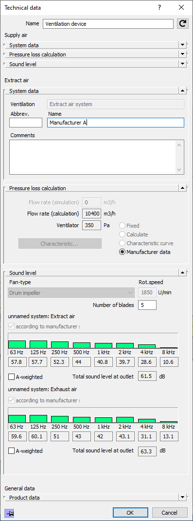
If you use a combined supply- and extract air device, the dialogs for both systems are combined into one.
You are here:

Name
Specifies the name of the component. You can modify the name. Clicking  restores the default setting.
System data
The system type is essential for the calculation. The flow direction has significant impact on the dynamically determined drag coefficient of the fittings. A number of plausibility checks for air duct network calculation are based on the correct system type. The system type results from the direction the ventilator symbol is pointing in your drawing. If you happen to have drawn it pointing in the wrong direction, you can simply rotate it automatically by selecting the proper system type (supply or exhaust air system).
Pressure loss calculation
The sub dialog Pressure loss calculation displays the calculated total air flow rate and the necessary (external) ventilator compression.
Volume flow rate (simulation):
The volume flow rate determined via simulation is displayed for your information.
If no simulation is selected, the field is deactivated.
Volume flow rate (Dimensioning):
For your information, the cumulative volume flow rate of all outlets considering all volume flow rate changes caused by temperature differences is displayed here.
Ventilator compression: By default, the ventilator compression is calculated. The following options are available:
-
Option fixed: Here a constant fan pressure should be specified as target flow rate. In the event of simulation, the specification corresponds to a constant pressure of a (constant) differential pressure regulation of the ventilator.
-
Option Calculate: In this case, the pressure is determined in the working point of a ventilator. Simulation is not possible for this option.
-
Option Characteristic curve: Here, you can enter the true characteristic curve with at least two value pairs for volume flow rate/compression, taken from a manufacturer catalog e. g. The preset characteristic curve can then be used for the dimensioning and simulation of the duct network.
The characteristic curve is intended to work with all established ventilators and regulating devices. The three most important characteristic curves are:
-
constant characteristic curve, e. g. with constant differential pressure control
-
linear characteristic curve, e. g. with variable differential pressure control
-
quadratic characteristic curve, e. g. for ventilators without regulation
The smallest and largest entry for the volume flow rate is used to verify that the calculated and simulated volume flow rates are within this volume flow rate interval. If an interpolation is necessary, a message will be issued in the report.
-
Manufacturer data: If manufacturer data is stored for the ventilation device, the radio button will be visible and activated after calculation. The calculated volume flow rate of the ventilator is output in the Volume flow rate (Dimensioning) field after successful calibration against the value stored in the manufacturer's data with a tolerance of 1 %. The calculated ventilator pressure build up required for the duct network is compared with the manufacturer's specifications with a tolerance of 5 % and displayed in the field Ventilator compression. If the tolerances are exceeded, reports are output. By comparing the calculated values with the manufacturer's specifications, it is ensured that the sound levels stored in the manufacturer's specifications are complied with.
Sound level
For combined supply and exhaust air device, the octave bands of the sound levels on the suction and pressure side are displayed. The sound level of the octave bands is calculated on the basis of the type, speed and, if necessary, the number of blades.
Fan-type: Drop-down list to select the fan-type. If manufacturer data is stored for the device, the field is deactivated and shows the fan-type stored in the manufacturer data.
Rot. speed: Allows the rotation speed to be specified manually. If manufacturer data is stored for the device, the field is deactivated and displays the value from the manufacturer data.
Number of blades: Allows you to specify the number of fan blades for the sound level calculation. If manufacturer data is stored for the device, the number of blades has no effect on the sound levels.
Sound level calculation:
Activated: The sound level is calculated according to VDI 2081. If manufacturer data is stored for the device, the check box is hidden.
acc. to manufacturer specifications: Displayed when values from manufacturer data are used.
The residual sound level at the outlet can be either A-weighted for all octave bands or not be weighted at all.
Product data
For information on this section of the component data, see the page Details on pressure loss calculation, Sound level, Duct material/Insulation and Product data in the Component data.