Details on Technical Data for Pipes
Information on the technical data dialog for pipes.
Pipes are always drawn as lines in the drawing. The program recognizes the pipe type (Gas pipe) by the layer on which these lines are located. A pipe may be connected at each end to a maximum of three other pipes (crossing T-piece) or one block symbolizing another component. It is neither possible to connect several pipes to a component connection nor to leave pipe ends open.
Fittings (Elbows, T-pieces) have to be used at branches. For open pipe ends, use the partial network end component or a pipe end. Do not set a partial network end unless it is to be linked to a partial network start.
The pipe type is determined either from the default that you set in the Pipe tables or by the separate definition of the pipe.
You are here:
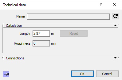
Name
Shows the name of the component. You cannot modify the name.
Calculation
Length: Here, the drawn length is displayed. You can change the value manually and have it reset to the drawn length by clicking Reset.
Roughness: The specified Roughness is the value taken from the relevant pipe table.