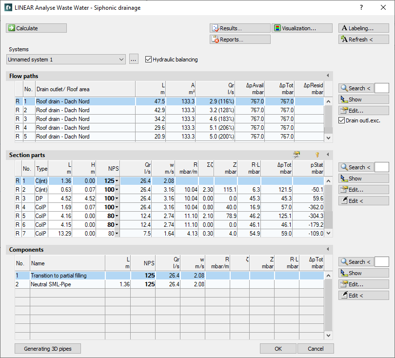
Details on the Calculation Dialog for Siphonic Drainage
Information about the dialog Analyse Waste Water - Siphonic Drainage.
The calculation dialog shows an overview of the detected pipe network and contains all commands necessary for the calculation.
You are here:
Commands for the calculation
The commands in the upper part of the calculation dialog pertain to the entire pipe network.
| Element | Meaning |
|---|---|
 Calculate | Initiate the calculation of the pipe network after having made changes to see current calculation results. |
| Systems | If the project contains several systems or partial networks you may determine which of the systems or partial network to display in the calculation dialog’s tables. |
| … | This button will open the technical data of the initial component. Here, you can change the system name shown in the drop-down list. |
| hydraulic balance | Enabled: Calculation is carried out immediately. The first step consists of dimensioning, the second of correcting volume flow rates until the resulting dpResid. disappears. Thereby one has a completely balanced system. If all dimensions of the system have been determined, the step for dimensioning is skipped and the volume flow rate is calculated. Disabled: The pipe network is dimensioned considering the available pressure, so far as section parts do not have fixed dimensions. The algorithm dimensions the network according to an available R-value and varies section parts until a dpResid. smaller than +/- 100 mb is reached. As soon as this goal has been achieved, the hydraulic load according to DIN 1986-100 is proven. It may very well happen, that a dpResid. smaller +/- 100 mb can not be held. |
 Result... | Displays additional information regarding the pipe network and an overview of the calculation results, which also are part of the printouts. |
 Report... | Displays an overview of notes and errors that occurred during calculation. The color of the button helps differentiate between notes and errors: white: No notes or errors. orange: There are notes on the calculation. red: There are errors in the calculation. Note: It is recommended to always carefully read the reports to correct errors in the drawing and ensure a proper calculation. |
 Visualization... | This command displays properties and calculation results of the pipe network in color in the drawing. |
 Labeling... | Label components and section parts with calculation results. |
 Refresh < | If components or section parts have already been labeled and calculation results have changed retrospectively, this button will refresh all labels with current data. |
Commands for the tables
In sections Flow paths, Section parts and Ventilated by section part(s) similar commands are presented.
| Element | Description |
|---|---|
 Maximize list | The tables of flow paths, section parts and ventilation section parts can be enlarged over the entire calculation dialog. The other tables are hidden. |
 Minimize list | Reduces a maximized table. The other tables are displayed again. |
 Search < | The command is available in the Flow paths, Section parts and Components sections. After clicking Search < select the element in the drawing. The respective table then shows the flow path, the section part or the ventilation section part. If a certain flow path number, a section part number or a ventilation section part number needs to be found, enter the number into the text field and click Search <. The respective table then shows the flow path, the section part or the ventilation section part. |
 Show | The command is available in the Flow paths, Section parts and Components sections. First, select the element from the table and click Show. The flow path, the section part or the ventilation section part is shown in the drawing. |
 Edit... | The command is available in the Flow paths, Section parts and Components sections. First, select the element in the table and click Edit.... The dialog for editing drainage element, section part or ventilation section part is opened. |
 edit in drawing < | The command is available in the Section part, and Components sections. After clicking edit in drawing <, select the element in the drawing. The dialog for editing section parts is opened. |
| Edit component data via drawing < | The command is available in the Components section. After clicking Editing component data via drawing <, select the component in the drawing. The dialog for editing the component is opened. |
Table for flow paths
This table shows the calculation data for all flow paths of the selected system. It provides an overview over all ending components of the network. If you select a flow path, the table Section parts displays all corresponding section parts. The most unfavorable flow path is highlighted in a different color. You can also select the most unfavorable flow path by pressing U.
Drain, eccentric
This command allows you to regulate and control the usage of eccentric transitions. To equip specific flow paths with eccentric transitions, mark the flow path in the table and click Edit. In the technical data of the roof drain you can activate the checkbox Use eccentric transitions.
Enabled: All section parts will use eccentric transitions.
Disabled: All section parts will use concentric transitions.
| Column | Description |
|---|---|
| (without title) | Pipe type: R: Rain water |
| No. | Flow path number. |
| Drain outlet / Roof area | Name of the roof drain or the gutter and corresponding roof area |
| L | Length of the flow path. |
| A | Roof area part of the roof drain. |
| Qr | Drain capacity (target- or actual volume flow rate). |
| dpAvail | Geodetic pressure recovery. |
| dpTot | Pressure loss of section part in this flow path. |
| dpResid | Error pressure difference of flow path. |
Table for section parts
This table shows the calculation data for all section parts of the selected flow path. If you select a section part, the table Ventilated via section part(s) displays all corresponding ventilation section parts.
 Unfix / fix section parts
This command allows you to fix or unfix the dimensions of all section parts. If values are displayed in bold in theDN column, the dimension of the respective section parts will not be adjusted during the calculation. This is sensible when calculating existing systems. If the dimensions of some section parts have been fixed already, you will be asked whether to fix or unfix all section parts.
 Split selected section part
Enables the division of a section part and inserts a reducer. This command is useful if you would like to use different materials or nominal diameters for a section part.
It may be necessary to adjust the layers to be considered for symbols in the Layer section of the Settings dialog in order to make the inserted transition symbol available in the calculation.
| Column | Description |
|---|---|
| (without title) | Pipe type: R: Rain water |
| No. | Number of the section part. |
| Type | DP: Down pipe G: Ground pipe ColP: Collector pipe C: Collecting pipe SCP: Single connector pipe (i): inside the building (o): outside the building Pipe type can be changed in the table. |
| L | Length of section part. The length be changed in the table. The new length will be distributed among all pipes of the section parts proportionately to constructed length. All pipes affected by the change in length will be displayed bold in the tables for section parts and components. |
| H | Height of section part. |
| DN | Nominal diameter of pipes in this section part. The nominal diameter can be changed in the table. The value is then fixed and will not be adjusted by the software during calculation. Fixed values are shown in bold. |
| Qr | Rainwater outflow rate. |
| v | Mean velocity. |
| R | R-value / pressure loss gradient |
| Sum zeta | Sum of zeta values due to single resistances. |
| Z | Pressure loss in mbar from velocity and zeta value. |
| R*L | Pressure loss due to pipe friction in this section part. |
| dpTot | Total pressure loss in this section part. Sum of R * L + Z. |
| pStat | Static pressure in mbar at the end of a section part calculated according to the law of the Bernoulli energy conservation equation. |
Table for components
This table shows the calculation data for all components of the selected section part.
| Column | Description |
|---|---|
| No. | Component number. |
| Name | Name of the component. |
| L | Length of the component. |
| DN | Nominal diameter of the component. |
| Qr | Rainwater outflow rate. |
| v | Mean velocity in this section part. |
| R | R-value / pressure gradient |
| Zeta | Zeta value of the single resistance. |
| Z | Pressure losses due to single resistances. |
| R*L | Pipe friction pressure loss due to single resistances. |
| dpTot | Total pressure loss of this component. Sum of R * L + Z. |
Generating 3D pipes
Allows the assignment of pipe materials from the 3D Piping module after the calculation of a single-line pipe network. After successful assignment, a three-dimensional pipe network is generated. Pre-assigned insulation material is considered. This process requires a license for the LINEAR 3D Design Pipe&Power module.